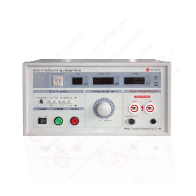
Working Principle of Withstand Voltage Tester:
Withstand Voltage Testing is a crucial process for assessing the ability of various electrical devices, insulation materials, and structures to withstand voltage. During the test, high voltage is applied to the insulation material without compromising its performance. The basic principle of a withstand voltage tester involves applying a voltage higher than the normal operating voltage to the insulation material of the device under test for a specified duration. If the insulation is intact, the applied voltage will only generate minimal leakage current. The purpose of this test is to verify whether the insulation performance of the tested equipment meets safety standards.
The working principle of a withstand voltage tester is outlined below:
• High Voltage Application: High voltage is applied to the insulation material of the tested device, exceeding its normal operating voltage.
• Duration: The applied voltage is maintained for a specified duration, typically according to industry standards or testing requirements.
• Leakage Current Detection: During the voltage application, the withstand voltage tester monitors the leakage current flowing through the insulation material of the tested device. If the leakage current remains within the specified range, it indicates good insulation performance.
• Voltage Reduction: After the test is completed, the applied voltage is gradually reduced to zero.
According to the provisions of IEC 61010, the test voltage must gradually increase to the required test voltage value (e.g., 5kV) within the specified time and be maintained on the tested insulation material for at least 5 seconds. After the test, the voltage must gradually decrease to zero within the specified time. Testing standards typically use a test voltage that is twice the working voltage of the device under test, plus an additional 1000V. Depending on the tested equipment, higher test voltages may be required.
WB2671B AC/DC Withstand Voltage Test
Structure and Components of Withstand Voltage Tester
The withstand voltage tester comprises several essential components that enable its operation. These components are categorized into the voltage boosting section, control section, and display circuit. Here’s a breakdown of the structure and components of a withstand voltage tester:
Voltage Boosting Section:
• Voltage Regulator: Used to adjust the voltage.
• Voltage Booster Transformer: Increases the input voltage to the required test voltage.
• Power On/Off Switch for the Voltage Boosting Section: Controls the connection and disconnection of the power supply to the voltage boosting section.
Control Section:
• Current Sampling Circuit: Monitors the current in the tested circuit.
• Timer Circuit: Controls the duration of the test.
• Alarm Circuit: Activates sound and light alarms when the current exceeds the set value and cuts off the power to the voltage boosting circuit.
Display Circuit:
• Display Screen: Shows the output voltage of the voltage booster transformer.
• Displays the current value and countdown time.
Test Duration of the Withstand Voltage Tester:
According to product standards and specifications, the duration of withstand voltage testing is typically set to 60 seconds. However, in production lines, prolonged testing often cannot meet practical needs as production lines prioritize speed and efficiency. Therefore, some organizations allow for the adjustment of testing time and voltage to achieve accuracy and efficiency. Some new safety standards also specify the setting of test duration. For example, in Appendix A of IEC 60335-1 and standards like IEC 60950-1, the test time for routine tests is set to 1 second. Thus, the ability to set the test duration is one of the essential functions of a withstand voltage tester.
https://www.lisungroup.com/news/technology-news/principle-and-structure-of-withstand-voltage-tester.html
.jpg)
Comments
Post a Comment