
An isolation transformer is a specialized transformer designed for electrical isolation. By providing electrical separation between the input and output windings, it helps prevent the risk of electric shock and ensures electrical safety. Initially, isolation transformers were widely used in the European power industry, and today they find extensive use in electronic industries, industrial and mining enterprises, machine tools, machinery, control power supplies, safety lighting, and indicator light power sources. Typically, isolation transformers have a 1:1 turns ratio, aimed at achieving high electrical isolation and suppressing common-mode interference.
1. Working Principle of Isolation Transformers
The core function of an isolation transformer is to provide electrical isolation between the AC power source (primary side) and the load (secondary side). Its primary uses include:
Electrical Isolation: Isolates the secondary winding from the ground to prevent electric shock.
Voltage Adjustment: Although isolation transformers typically maintain a 1:1 turns ratio, they can also be used for voltage stepping up or down in some cases.
Noise Suppression: Reduces line noise from the primary to the secondary winding and vice versa.
According to the energy conservation law for transformers, if losses are neglected, the product of the primary voltage (VP) and primary current (IP) equals the product of the secondary voltage (VS) and secondary current (IS). The rated power of the transformer is calculated by the product of the effective voltage and effective current on the primary winding, measured in volt-amperes (VA).
In the schematic diagram, the phasing point marks the direction of the primary and secondary currents. Accurate phasing is crucial for series or parallel configurations of windings. Faraday shielding is an electrostatic shielding technique used to reduce capacitive coupling between the primary and secondary windings, typically grounded. This shielding helps lower common-mode noise and transient signals through the transformer.
The primary and secondary windings in an isolation transformer are highly insulated to minimize direct conduction. Insulation performance is usually measured by leakage current, and most isolation transformers are also subjected to high-potential testing to ensure insulation quality.
2. Differences Between Isolation Transformers and Regular Transformers
The primary function of a regular transformer is to alter voltage, classified into step-down and step-up transformers, with differing turns ratios between the primary and secondary windings. Regular transformers focus on voltage conversion, while isolation transformers are centered around electrical isolation, typically having equal turns ratios (1:1). This design is intended to ensure electrical safety rather than voltage conversion. For example, pulse transformers used to prevent high voltage from entering pulse CNC devices are also applications of isolation transformers.
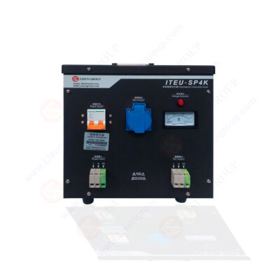
ITEU-SP4K Isolation Transformer
Unique aspects of isolation transformers include:
• Primary Grounding, Secondary Floating: The secondary winding is isolated from the ground to prevent electric shock.
• Isolation Layer Design: An additional isolation layer between the primary and secondary windings, grounded for effective isolation.
This design ensures that the secondary winding is not connected to the ground, avoiding risks of electrostatic interference and breakdown. Isolation transformers are commonly used to isolate impurities in mains power, ensuring equipment safety. Despite sharing the basic principles with regular transformers, the focus of isolation transformers is on electrical isolation. In addition to the 1:1 turns ratio, isolation transformers are used in various control power supplies and electronic devices, such as tube amplifiers, oscilloscopes, and lathe control transformers.
3. Typical Applications of Isolation Transformers
Isolation transformers are most commonly used to isolate equipment from the AC power source ground. Specific applications include:
• Switch-Mode Power Supplies (SMPS): In flyback topology SMPS, isolation transformers are used for electrical isolation to ensure safety and prevent short circuits. Electrical isolation is achieved through the transformer and optocouplers, allowing safe troubleshooting of primary circuits.
• Ground Loop Diagnosis and Correction: Isolation transformers are valuable for diagnosing and repairing ground loop issues, effectively isolating the source of ground leakage currents.
• High-Frequency Noise Reduction: By incorporating series inductance and Faraday shielding, isolation transformers reduce high-frequency noise transmitted from lines to equipment, enhancing the overall performance of electrical systems.
By providing electrical isolation and noise suppression, isolation transformers not only enhance the safety of equipment but also optimize the performance of electrical systems. https://www.lisungroup.com/news/technology-news/isolation-transformer-principles-applications-and-distinct-features.html
.jpg)
Comments
Post a Comment