Abstract
As the complexity of electronic devices continues to increase, ensuring electromagnetic compatibility (EMC) becomes essential to guarantee operational reliability. One critical component of EMC compliance is immunity testing, specifically radio-frequency (RF) immunity. This paper aims to answer the question: What is RF immunity test? Through a detailed discussion of RF conducted immunity testing methods, standards, and instrumentation, this paper highlights the functionality and advantages of the LISUN RFCI61000-6 RF Conducted Immunity Test System. It covers applicable standards, system architecture, test procedures, and presents technical specifications and performance data to offer a practical understanding of RF immunity testing.
1. Introduction
With the increasing presence of RF sources in everyday environments, electronic devices must demonstrate immunity to conducted RF disturbances. This is particularly crucial in industrial environments where electromagnetic interference (EMI) can severely impact device performance. Hence, RF immunity testing becomes a fundamental part of EMC compliance.
This paper explores the concept of “What is RF immunity test?” through the lens of the LISUN RFCI61000-6 system, a specialized solution for RF conducted immunity testing, designed in compliance with international standards like IEC/EN 61000-4-6.
2. What is RF Immunity Test?
The RF immunity test is a type of EMC immunity test that evaluates an electronic product’s ability to operate normally in the presence of RF disturbances. Specifically, RF conducted immunity refers to testing for conducted RF disturbances that are injected into the power or signal lines of a device under test (DUT).
2.1 Purpose of RF Immunity Testing
The goal of RF immunity testing is to ensure that electrical and electronic equipment maintains functional integrity when exposed to RF signals. These signals can originate from intentional sources (such as radios, cellular devices) or unintentional sources (such as switching power supplies or motors).
2.2 Standards Involved
The primary standards governing RF conducted immunity testing include:
• IEC/EN 61000-4-6: Immunity to conducted disturbances, induced by radio-frequency fields.
• IEC/EN 61000-6-1/2/4: Generic immunity standards for residential, industrial, and commercial environments.
RF Conducted Immunity Test System RFCI61000 6
3. Overview of the LISUN RFCI61000-6 System
The LISUN RFCI61000-6 is a comprehensive RF conducted immunity test system that complies with IEC 61000-4-6. It enables efficient and precise testing for immunity to conducted RF disturbances within the frequency range of 150 kHz to 230 MHz.
3.1 Key Features
• Fully compliant with IEC/EN 61000-4-6
• Frequency range: 150 kHz – 230 MHz
• Output power up to 100 W
• Automatic calibration and control software
• Compatible with CDN (Coupling/Decoupling Networks), EM clamps, and direct injection probes
3.2 System Components
Component
Description
RF Signal Generator
Generates modulated RF signals over the required frequency range
RF Power Amplifier
Amplifies the signal to the required test level (up to 100 W)
Coupling/Decoupling Network (CDN)
Couples the RF signal into the power or signal lines of the DUT
EM Clamp or Injection Probe
Alternative injection methods for non-standard cables
Power Meter & Directional Coupler
Measures forward and reflected power to ensure consistent injection levels
Calibration Kit
For system calibration according to IEC 61000-4-6
Control Software
Automates the test setup, calibration, execution, and reporting
4. Test Configuration and Procedure
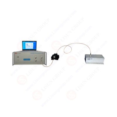
4.1 Typical Test Setup
The test setup includes the DUT, LISUN RFCI61000-6 system, appropriate CDN or injection method, and a shielded test environment to minimize ambient noise. A typical test configuration is shown below:
• Connect the signal generator to the RF amplifier.
• Connect the amplifier output to the CDN via a directional coupler.
• Insert the DUT’s power/signal cable through the CDN.
• Use the control software to initiate and monitor the test.
4.2 Calibration
Before the actual test, a substitution method is used to calibrate the system:
• A 6 dB attenuator replaces the DUT.
• The desired voltage level is verified using the power meter.
• The control software stores the required amplifier drive levels for each frequency step.
4.3 Testing
• The system sweeps through the frequency range (150 kHz–230 MHz).
• Each frequency step is maintained for a specified dwell time (e.g., 3 seconds).
• Modulation (typically 80% AM at 1 kHz) is applied to simulate real-world disturbances.
5. Technical Specifications
The table below summarizes the specifications of the LISUN RFCI61000-6 RF Conducted Immunity Test System.
Specification
Value
Frequency Range
150 kHz – 230 MHz
Output Power
Up to 100 W
Modulation
80% AM @ 1 kHz (per IEC 61000-4-6)
Impedance
50 Ohms
Voltage Output Range (CDN)
Up to 10 V (calibrated level)
Calibration Method
Substitution method (per IEC standard)
Control Software
Windows-based GUI with report output
Power Supply
220V AC ±10%, 50/60Hz
Dimensions
System dependent (modular)
6. Advantages of LISUN RFCI61000-6
Standard Compliance: Adheres strictly to IEC/EN 61000-4-6 requirements.
• User-Friendly Software: Intuitive GUI reduces operator error and test time.
• High Reliability: Accurate and repeatable results with automatic calibration routines.
• Flexible Configuration: Compatible with various types of CDNs and injection probes.
• Wide Application: Suitable for testing power electronics, control systems, home appliances, automotive components, and industrial devices.
7. Application Scenarios
7.1 Industrial Automation
In factory automation, devices like PLCs and motor drives are susceptible to conducted RF noise from nearby machinery. The LISUN system ensures these devices maintain performance even under harsh EMI conditions.
7.2 Medical Equipment
RF immunity is critical in medical environments where wireless communication and other RF sources could interfere with life-support systems. The LISUN RFCI61000-6 is ideal for pre-compliance and compliance testing of such sensitive devices.
7.3 Consumer Electronics
With the proliferation of smart home devices, ensuring immunity to RF disturbances becomes essential for user satisfaction and regulatory approval.
8. Case Study: RF Immunity Testing on a Smart Home Hub
A smart home hub with integrated Wi-Fi and Zigbee interfaces was tested using the LISUN RFCI61000-6. The DUT was subjected to 10 V RF signal over 150 kHz–230 MHz via CDN.
Test Results Summary:
Frequency Range
Injected Voltage
Observed Behavior
Verdict
150–500 kHz
10 V
Normal operation
Pass
500 kHz–30 MHz
10 V
Temporary delay in response
Pass (no malfunction)
30 MHz–230 MHz
10 V
No effect
Pass
The hub maintained functional integrity across all test bands, confirming its robustness in noisy RF environments.
9. Summary and Conclusion
This paper addressed the question “What is RF immunity test?” by exploring both the theoretical and practical aspects of RF conducted immunity testing. The LISUN RFCI61000-6 RF Conducted Immunity Test System emerged as a comprehensive and effective solution for RF immunity evaluations. Its robust architecture, compliance with global standards, and user-friendly interface make it suitable for a wide range of testing needs.
In conclusion, as electronic systems continue to integrate into all aspects of modern life, RF immunity testing ensures these devices perform reliably amidst increasingly complex electromagnetic environments. The LISUN RFCI61000-6 stands as a powerful tool in this essential testing domain.
References
• IEC 61000-4-6: Electromagnetic compatibility (EMC) – Part 4-6: Immunity to conducted disturbances, induced by radio-frequency fields.
• IEC 61000-6-1/2/4: Generic immunity standards.
• LISUN Group Official Website – RFCI61000-6 RF Conducted Immunity Test System
• Electromagnetic Compatibility Engineering – Henry W. Ott https://www.lisungroup.com/news/technology-news/what-is-rf-immunity-test-an-in-depth-analysis-of-the-rf-conducted-immunity-test-system-based-on-the-lisun-rfci61000-6.html


.jpg)
Comments
Post a Comment